Simultaneous aortography and left ventriculography for transcatheter valve-in-valve implantation in patients with a stentless bioprosthetic aortic valve
Supported by the EuroIntervention Journal
Thanks to this image in cardiology, watch how an 82-year-old female patient underwent transcatheter ViV implantation for symptomatic severe SVD of the stentless pericardial bioprosthesis that had been implanted 4 years ago.
Authors1
Takayuki Onishi, Motoki Fukutomi, Tomo Ando, Tetsuya Tobaru
Case summary
An 82-year-old female patient underwent transcatheter valve-in-valve implantation for symptomatic severe structural valve degeneration (SVD) of Solo Smart (Sorin Group, Saluggia, Italy), a stentless bovine pericardial bioprosthesis that had been implanted four years ago.
The stenotic 21-mm valve with an effective orifice area of 0.62 cm2, peak flow velocity of 4.2 m/s, and trivial regurgitation on transthoracic echocardiography (Movie 1) caused exertional dyspnoea.
Preoperative computed tomography (CT) showed diffusely thickened leaflets with scarce calcification (Figure 1A).
Based on the CT measurements of the annulus perimeter of 54.3 mm and the surface area of 230.9 mm2, we selected a 23-mm Evolut Pro+ (Medtronic, Minneapolis, Minnesota, US). The thickness of the noncoronary cusp measured on CT was 4.5 mm (Figure 1B).
Aortography clearly showed the inside margin of the thickened leaflet on the aortic side (Figure 1C and Movie 2).
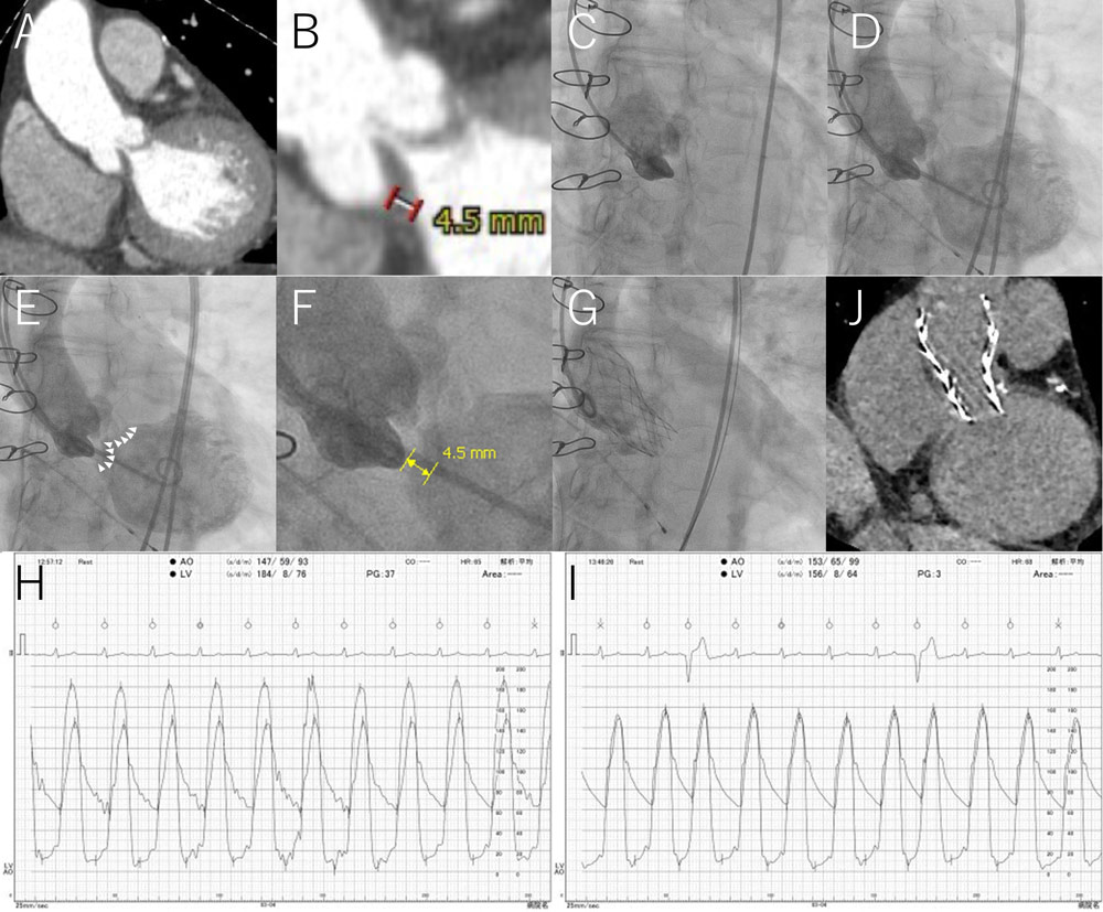
Figure 1. SAL technique for stentless bioprosthetic valves
All figures represent the same perpendicular view (16-degree left anterior oblique and 15-degree caudal).
(A) Preoperative CT. Leaflets were diffusely thickened with scarce calcification.
(B) Preoperative CT. Magnified view. The thickness of the noncoronary cusp measured on CT was 4.5 mm.
(C) Preprocedural aortography. The aortic-side margin of the thickened leaflet was clearly shown.
(D) SAL. Simultaneous aortography and left ventriculography showed the whole thickened valve as radiolucent.
(E) SAL. White arrowheads indicate the ventricular margin of the thickened valve, which can be a deployment landmark for valve-in-valve implantation.
(F) SAL. Magnified view. The noncoronary cusp thickness was 4.5 mm, which was the same as the CT-derived thickness (Figure 1B).
(G) Postprocedure aortography. A 23-mm Evolut Pro+ was implanted by reference to the negative contrast valvulography.
(H) Preprocedural left ventricular and aortic pressure tracing. The preprocedural pressure gradient between the left ventricle and aorta was 37 mmHg.
(I) Postprocedural left ventricular and aortic pressure tracing. The postprocedural pressure gradient between the left ventricle and aorta was 3 mmHg. The diastolic aortic pressure was 65 mmHg.
(J) Postprocedural CT. The valve was implanted at a suitable position with its lower strut edge located at the bottom of the degenerated valve, which was estimated from comparison with Figure 1A.
However, it was difficult to identify the ventricular margin of the thickened leaflet, which was the target of transcatheter valve implantation.
Furthermore, it was challenging to determine the appropriate deployment position on the live display using the CT-derived information of the noncoronary cusp thickness of 4.5 mm. Our angiography suite did not have the capacity to merge the angiogram and the CT image.
Therefore, we performed simultaneous aortography and left ventriculography, which showed the whole thickened valve as radiolucent (Figure 1D, 1E and Movie 3).
Quantitative assessment of the simultaneous injection image revealed a noncoronary cusp thickness of 4.5 mm (Figure 1F), which was the same as the CT-derived thickness (Figure 1B).
We successfully implanted Evolut Pro+ in reference to the negatively contrasted leaflet image (Figure 1G and Movie 4).
The pressure gradient between the left ventricle and aorta decreased from 37 mmHg to 3 mmHg after implantation (Figure 1H and 1I). The diastolic aortic pressure was maintained at 65 mmHg (Figure 1I).
There was no significant perivalvular regurgitation on aortography (Movie 4) or transthoracic echocardiography (Movie 5) after the procedure.
Therefore, we decided not to perform postdilation.
Postprocedural CT showed that the valve was implanted at a suitable position, with its lower strut edge located at the bottom of the degenerated valve (Figure 1J).
Take-home messages
The lack of fluoroscopic visibility of a stentless bioprosthetic valve makes valve-in-valve implantation a challenging procedure1.
Furthermore, in the present case, aortography alone failed to reveal the target position for valve implantation due to the thickened leaflet with scarce calcification2.
The simultaneous aortography and left ventriculography (SAL) technique provided a positional relationship between the reference pigtail catheter in the noncoronary cusp and the bottom of the thickened valve, effectively guiding valve implantation. The present technique is useful for the valve-in-valve procedure for stentless bioprosthetic valves.
The depth of transcatheter heart valve implantation can be predicted and simulated with CT.
In the present case, however, it was difficult to specifically determine the optimal deployment position, that is 4.5 mm below the inside margin of the thickened leaflet at the aortic side, by conventional aortography alone.
SAL concretely indicated the optimal deployment position on the live display for operators.
References
- Duncan A, Moat N, Simonato M, de Weger A, Kempfert J, Eggebrecht H, Walton A, Hellig F, Kornowski R, Spargias K, Mendiz O, Makkar R, Guerrero M, Rihal C, George I, Don C, Iadanza A, Bapat V, Welsh R, Wijeysundera HC, Wood D, Sathananthan J, Danenberg H, Maisano F, Garcia S, Gafoor S, Nombela-Franco L, Cobiella J, Dvir D. Outcomes Following Transcatheter Aortic Valve Replacement for Degenerative Stentless Versus Stented Bioprostheses. JACC Cardiovasc Interv. 2019;12:1256-1263.
- Della Barbera M, Pettenazzo E, Livi U, Mangino D, Gerosa G, Bottio T, Basso C, Valente M, Thiene G. Structural valve deterioration and mode of failure of stentless bioprosthetic valves. Cardiovasc Pathol. 2021;51:107301.
Affiliations
- Department of Cardiology, Kawasaki Heart Center, Kawasaki Saiwai Hospital, Kawasaki, Japan
Conflict of interest statement
The authors have no conflicts of interest to declare in relation to the content of this article.

No comments yet!