How to choose a snare and create a snare to enhance device trackability in structural interventions
A problem-solving step by step tutorial
Transcatheter structural procedures are dramatically increasing in daily practice. Approaching hostile cardiac anatomy may increase the risk of device dislodgment and/or malposition. In such situations, the use of a snare catheter is pivotal to enhance device trackability.
Frequency of the problem:
Expert level:
Summary
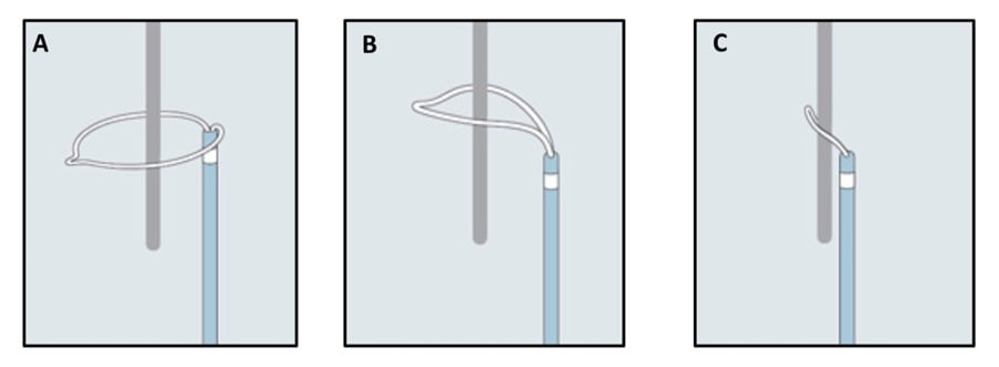
A snare is an endovascular device that consists of one or more radiopaque loops of wire inserted in a catheter, which, when extended, flower out, and, when withdrawn into the catheter, collapse. Its main function is to capture, within the extended loop/loops, any lost or malpositioned devices, with the final aim to retrieve and/or reposition them once its loop/loops are collapsed (Figure 1a. A-C).
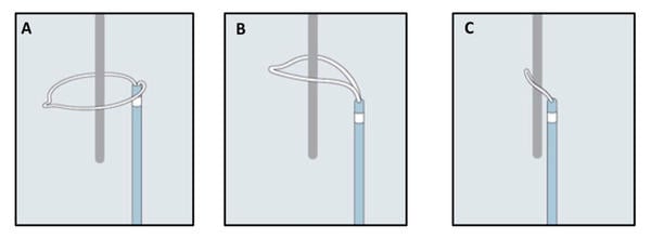
Figure 1a - How a snare works (A-C). A) Snare catheter in the extended configuration (flowered out); B) Once the capturable body is inside the loop, the snare is tightened; C) The foreigner body is secured by the snare and is ready to be retrieved.
Once vascular access is obtained, the snare is usually inserted through a guiding catheter and placed in proximity to the capturable device.
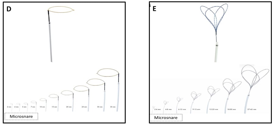
Many types of snare are available. They vary according to different characteristics: the size of the catheter, its length, and the number and working diameter of its loops. Based on the numbers, snaring systems can be classified into single configurations (e.g Amplatz Goose Neck, Medtronic, or One Snare, Endovascular snare), or multiple overlapping loop configurations (e.g. En Snare, Endovascular snare). Both configurations are available in several different working loop diameters, ranging from a few millimeters (2 to 7 mm, also called microsnare) to some centimeters (up to 35-45 mm) (Figure 1b. D-E).

Figure 1b - Different types of snare (with different dimensions) (D-E). D) Single-loop snare; E) Multi-loops snare.
The Problem
The choice of snare type and size largely depends on the type and location of the embolized devices, and the planned retrieval technique.
Although capturing a small device, or one of its small components, may be feasible with a small-diameter loop snare, it appears challenging to succeed if the embolized device is not over a wire, or if its coaxiality with the snare is difficult to achieve. On the contrary, if the purpose is to encircle the entire device, a large snare is required.
On the other hand, the localization of the capturable device, in terms of vessel or cardiac dimensions, is pivotal to safely choose the size of the snare and to avoid traumatic lesions.
Repositioning of a partially embolized device
Device malpositioning can occur during cardiac structural interventions. In some cases, the incorrectly released device may still be repositioned in the proper location. Figure 2 illustrates a case of PFO occluder, which, immediately after its release, showed incomplete adherence of its left-side lobe to the septum secundum. Advancing a large (30 mm) loop snare system inside a 7 Fr guiding catheter made it possible to embrace the small metallic left-side bump (used to connect the delivery cable) of the occluder (Figure 2. A-B) and, once the snare has been clamped, to bring the whole device back into correct position (Figure 2. C-D and Video 1). This example highlights the importance of being aware of the presence of “protruding”, and so potentially “snarable”, components of the different devices used in clinical practice.
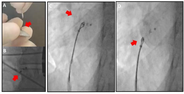
Figure 2 – PFO occluder repositioning. A-B) Protruding metallic bump of PFO occluder, which represents the target for the snaring. C) Occluder snaring and D) repositioning (by a pulling back maneuver of the snare).

Bailout removal of a released device
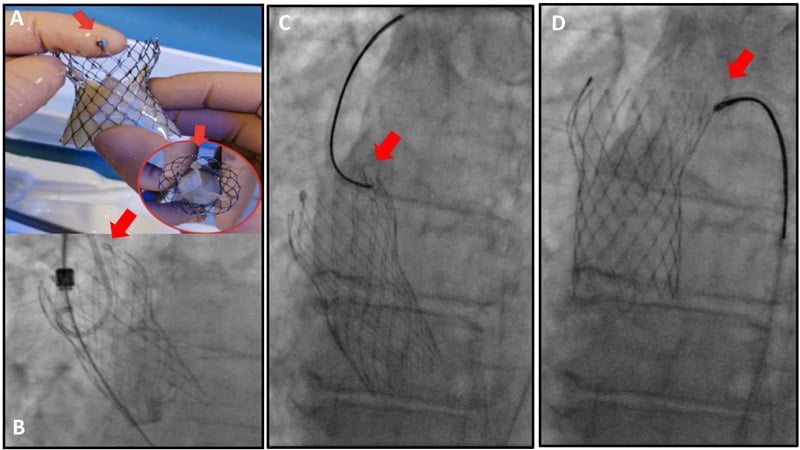
A snare catheter also represents a valuable tool in bailout scenarios. This is the case of a properly released transcatheter heart valve (THV) during a TAVI procedure, complicated by acute coronary occlusion due to small aortic root anatomy. An intentional pop-up was performed using a 30 mm loop snare, which captured the C-tab of the valve (in this case, Evolut platform, Medtronic) (Figure 3. A-C). Exerting significant traction, the valve was removed from its original annular position and placed distally to the aortic arch (Figure 3. D). This manoeuvre immediately restored coronary perfusion (Video 2).

Figure 3 – Intentional bail-out THV pop-up. A-B) Protruding and “snarable” component of the THV (C-tab); C) C-tab snaring with a large single-loop device; D) Traction and removal of the implanted THV from the annular position.
Yet, in this scenario, it is essential to recognize the presence of a “snarable” component of the single device. In fact, not all THVs can be directly snared (e.g Acurate platform – Boston Scientific): in this circumstance, a workhorse guidewire has to be passed below the THV stent struts (ideally those located at the THV outflow) and then snared into the aorta to create a loop (Figure 4. A-B). A second snare may be used to anchor the lower crown of the bioprosthetis (“double snaring technique”) to increase the pull-back force (Figure 4. C-D and Video 3).
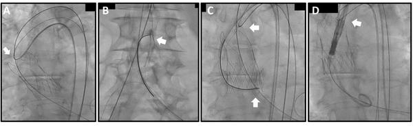
Figure 4 – Double snaring of an embolized THV. Given the absence of “snarable” component in the upper part of the embolized THV (in this case, Acurate platform), a guidewire has been advanced below one of the three stabilization arches (A) and then snared in the abdominal aorta (B); this maneuver allows to create a first loop; to perform an intentional THV pop-up, a second snare was used to tie the THV at the lower crown (“double snaring technique” in C); the upper loop was used to keep in position the embolized THV during the advancement of a second THV (D).

Increasing THV trackability
None of the commercially available self-expanding THVs used in TAVI procedures has a deflectable delivery system, allowing the operator to flex and shape it by turning a dial. To overcome this drawback, the use of a snared catheter can act as an external traction force, able to redirect the delivery system as it navigates, particularly through the aorta. Challenging situations requiring the use of a snare catheter may include the presence of a previously implanted bulky bioprosthetic heart valve, a gothic aortic arch, a porcelain aorta, and the presence of an embolized THV4. The use of a large loop snare catheter can either be planned (meticulous CT analysis can detect the previously mentioned anatomical challenging scenarios in advance) or adopted in a bailout scenario. If planned (Figure 5 and Video 4), the snare is usually placed through the contralateral femoral access and flowered out in the descending aorta to allow the passage of the material needed to cross the aortic valve (e.g Amplatz catheter).
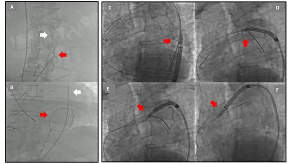
Figure 5 – Planned THV snaring due a gothic aortic arch. A-B) Placing a large single-loop snare in the descending aorta in a flowered-out configuration (red arrows) allows the passage of guidewire and catheter through it, before crossing the aortic valve. C) Once the stiff wire is placed in the left ventricle, the THV delivery system is advanced and the snare is tightened at its nosecone. D-E) When the snare is pulled back, a traction is reflexed on the THV system, able to change its trajectory during aortic arch advancement. F) Loosen snare.
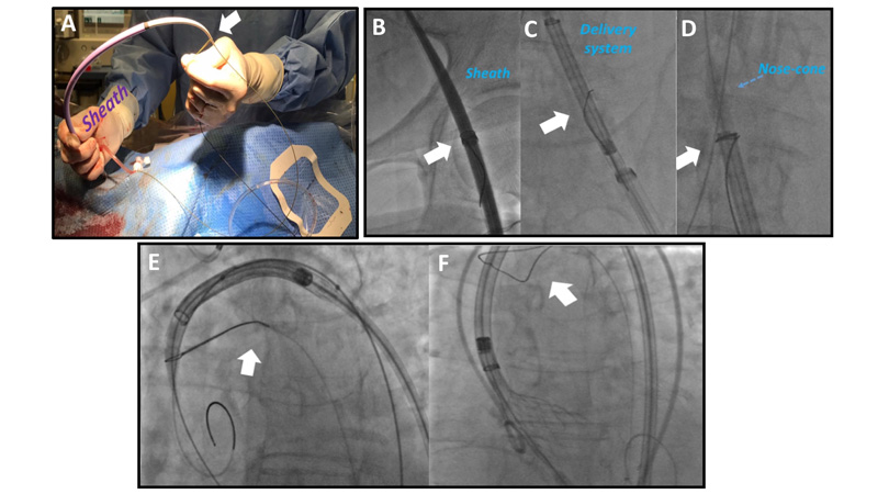
On the other hand, if the complication is not predictable, a bailout use of the snare is possible via the ipsilateral access (Figure 6 and Video 5). In such case, contralateral snare insertion also requires removal of the guidewire from the left ventricle, whereas ipsilateral insertion (pre-mounting of the snare on the tip of the sheath) does not. It is important to note that only sheathless THVs may be snared in a bailout fashion: removal of the guidewire from the ventricle is not feasible if THV is not completely retrievable into its sheath (e.g Acurate or Sapien platforms).

Figure 6 – Bail-out THV snaring due to a porcelain aorta. A) A single-loop snare catheter positioned externally on 18 Fr femoral sheath; B) the snare (white arrow) tied on the sheath after insertion in the vessel; C) the snare (white arrow) positioned and tied at the level of THV's nose-cone after its insertion; D) traction force allowing THV's advancement, witnessed by reduction of the angle pointed-out by white arrow; E) snare (white arrow) removal during valve implantation.
Unfrequent TAVI scenarios
A snare catheter is an indispensable tool in rare but game-changing TAVI scenarios, such as alternative access (transcaval TAVI) and bioprosthetic or native aortic scallop intentional laceration to prevent iatrogenic coronary artery obstruction (BASILICA).
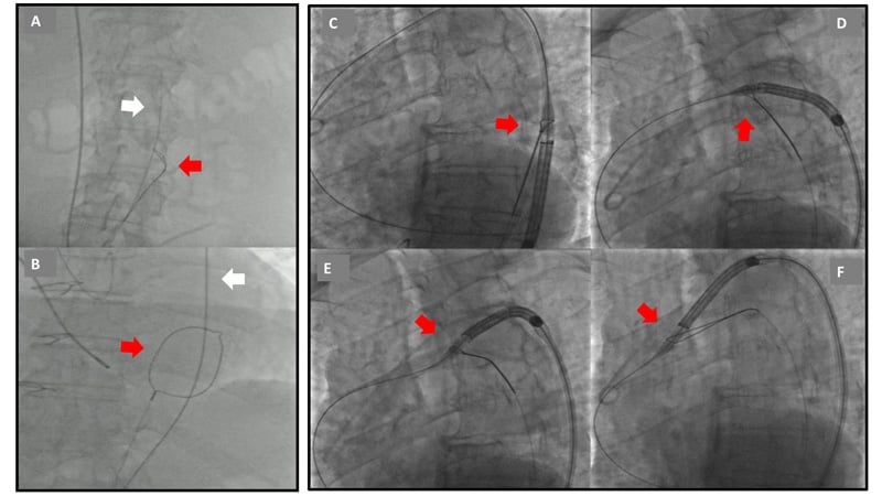
In transcaval TAVI, a single-loop aortic snare is introduced via a 5 or 6 Fr guiding catheter (typically JR4) into the abdominal aorta5. The snare is selected to be at least 5 mm larger than the aortic lumen diameter at the target site (for example, a 20 mm snare is selected for a 15 mm aorta), to enable appropriate positioning. Multiple loop snares are not a satisfactory alternative to gooseneck-design snares as they provide ambiguous targets. The aortic snare serves as a “bulls-eye” target for the wire advanced in the inferior vena cava, and their coaxiality has to be checked on orthogonal projections (Figure 7. A-B). Once the guidewire has crossed the vein and arterial walls, the snare is tied to capture the guidewire and then, both in tandem, are advanced up to the thoracic aorta (Figure 7. C-D and Video 6).
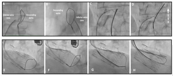
Figure 7 – Snare use during trans-caval TAVI (A-D). A-B) A large single-loop snare is positioned in the abdominal aorta and serves as markers for the electrified wire placed in the inferior vena cava. Their co-axiality has to be confirmed in different angiographic projections; C) Guidewire snaring after its passage from the vena cava to abdominal aorta; D) The entire system is advanced, pushing the snare catheter towards the thoracic aorta. Snare use during BASILICA (E-H). E) Snare position in the LVOT through a multipurpose guiding catheter; F-G) the guidewire use for leaflet traversal is then snared in the proximal LVOT; H) guidewire invagination into multipurpose guiding catheter creates the “V-shape” system able to intentionally lacerate the aortic leaflet.

Similarly, BASILICA requires the use of snare catheter6. After crossing the aortic valve, a 6 Fr multipurpose guiding catheter is advanced. Subsequently, a 0.025-inch curved wire is delivered to the left ventricle apex. A snare is then introduced through the guiding catheter into the left ventricular outflow tract (LVOT), parallel to the 0.025-inch wire (Figure 7. E). The snare size is determined by the LVOT diameter at 5-10 mm below the annulus. Between two snare sizes, it is reasonable to select an undersized snare, since a snare that is too large does not form well in the LVOT. The optimal snare position is considered to be close to a straight line in the LVOT in both cusp front and side projections. The snare should be placed 5-10 mm below the aortic annulus to provide a good landmark for the crossing. Once the leaflet has been crossed successfully, the wire is commonly already inside the snare loop and wire snaring is not necessary (Figure 7. B-C). Snaring must be performed in the proximal LVOT to avoid damage to the mitral valve apparatus. Once snaring is achieved, the wire is invaginated inside the guiding catheter and drawn back to the ascending aorta, forming a “V-shape” system, intentionally used to lacerate the leaflet (Figure 7. D and Video 7)
Principal idea
Snaring is not often used in daily practice but, as seen before, it can be an important tool. Due to its infrequent use, desired dimensions of snare devices in the cathlab are limited and not always suitable for the specific situation. It may be of interest to know that a “homemade” snare can be created in few steps [also called KAM-snare7,8]. The homemade snare is size-adjustable and can be applied to catch different foreign bodies.
Material needed
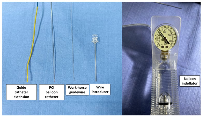
The material used for a homemade snare is depicted in Figure 8 and consists of:
- A conventional (workhorse) 0.014” guidewire
- A 2.0 mm semi-compliant balloon catheter
- A 6 Fr guide catheter extension (GCE)
- A balloon indeflator
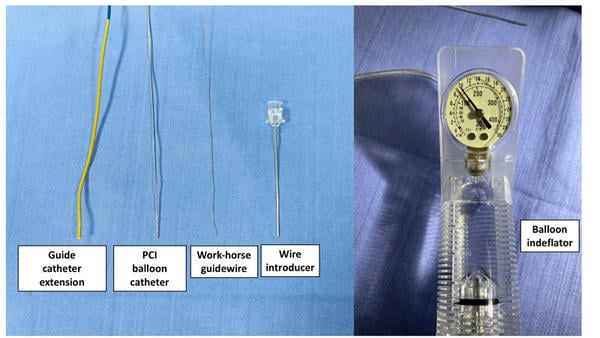
Figure 8 – Material needed to create a homemade snare.
Method step-by-step
Step 1
The 0.014” guidewire is inserted into the wire lumen of the 2.0 mm semi-compliant balloon and advanced until it protrudes 20-30 mm from the balloon tip.
Step 2
The guidewire tip is folded back towards the balloon in a loop fashion, then the whole system is inserted in the 6 Fr GCE (Figure 9. A) and advanced up to 10 mm from the tip (Figure 9. B-C)
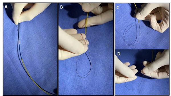
Figure 9 – Step by step homemade snare construction. A) A conventional guidewire and a 2.0 mm balloon are inserted into a 6 Fr guide catheter extension (GCE); B) the proximal end (10-20 mm) of the guidewire is looped inside the (GCE) and trapped by the inflated balloon; C-D) Advancing the distal end of the guide wire is possible to modulate the dimension of the homemade snare’s loop.

Step 3
The folded guidewire is trapped by balloon inflation (usually 8-12 atm) into the GCE.
Step 4
Advancement of the guidewire shaft will produce a size-adjustable snare loop (Figure 9.D and Video 8)
A word from the reviewer - Dr Alexander Völz

It is well known that the primary role of a snare is to retrieve any lost or malpositioned device.
However the above depicted cases impressively demonstrate the „alternative“ utilization of snare-assisted techniques in a wide range of interventional scenarios in order to master anatomically complex situations and technical challenges.
References
- Lederman RJ, Babaliaros VC, Greenbaum AB. How to perform transcaval access and closure for transcatheter aortic valve implantation. Catheter Cardiovasc Interv. 2015 Dec 1;86(7):1242-54. doi: 10.1002/ccd.26141. Epub 2015 Sep 10. PMID: 26356244; PMCID: PMC4740457.
- Komatsu I, Mackensen GB, Aldea GS, Reisman M, Dvir D. Bioprosthetic or native aortic scallop intentional laceration to prevent iatrogenic coronary artery obstruction. Part 2: how to perform BASILICA. EuroIntervention. 2019 May 20;15(1):55-66. doi: 10.4244/EIJ-D-19-00056. PMID: 30888958.
- Mashayekhi K, Valuckiene Z, Neuser H, Akin I, Reifart N, Toma A, Neumann FJ, Behnes M. Wire externalisation techniques for retrograde percutaneous coronary interventions of chronic total occlusions. EuroIntervention. 2017 Dec 8;13(12):e1489-e1490. doi: 10.4244/EIJ-D-16-00009. PMID: 29208580
- Yokoi K, Sumitsuji S, Kaneda H, Siegrist PT, Okayama K, Ide S, Mizote I, Kumada M, Kuroda T, Tachibana K, Sakata Y, Nanto S. A novel homemade snare, safe, economical and size-adjustable. EuroIntervention. 2015 Mar;10(11):1307-10. doi: 10.4244/EIJV10I11A220. PMID: 24642569
View "How to create a snare in coronary interventions"
Authors


No comments yet!